Learn more about Elevator World, the top trade magazine for the Elevator Industry.
(Note – Article text is also provided below article pages for easier reading on certain devices)
Spanning the Distance – Lake Erie Inclined Lift
by Bill MacLachlan
Lakeview, New York, overlooks Lake Erie, providing nearby residents a stunning view. It is also home to one of Hill Hiker Inc.’s most challenging inclined elevator installations. The owners of a private residence were searching for a way to not only enjoy the lake’s view, but also be able to access the beach.
When Hill Hiker accepted the project, the most difficult issues it initially faced were the steep cliff (in excess of 60°) with unstable soil conditions and severe storm surges. Due to the shallow nature of Lake Erie (a maximum depth of approximately 60 ft.), when a storm rolls in the surge that hits the shoreline can be enormous. Hill Hiker worked with Urban Engineers to design an integral structure on which the Hill Hiker® inclined elevator could be securely mounted.
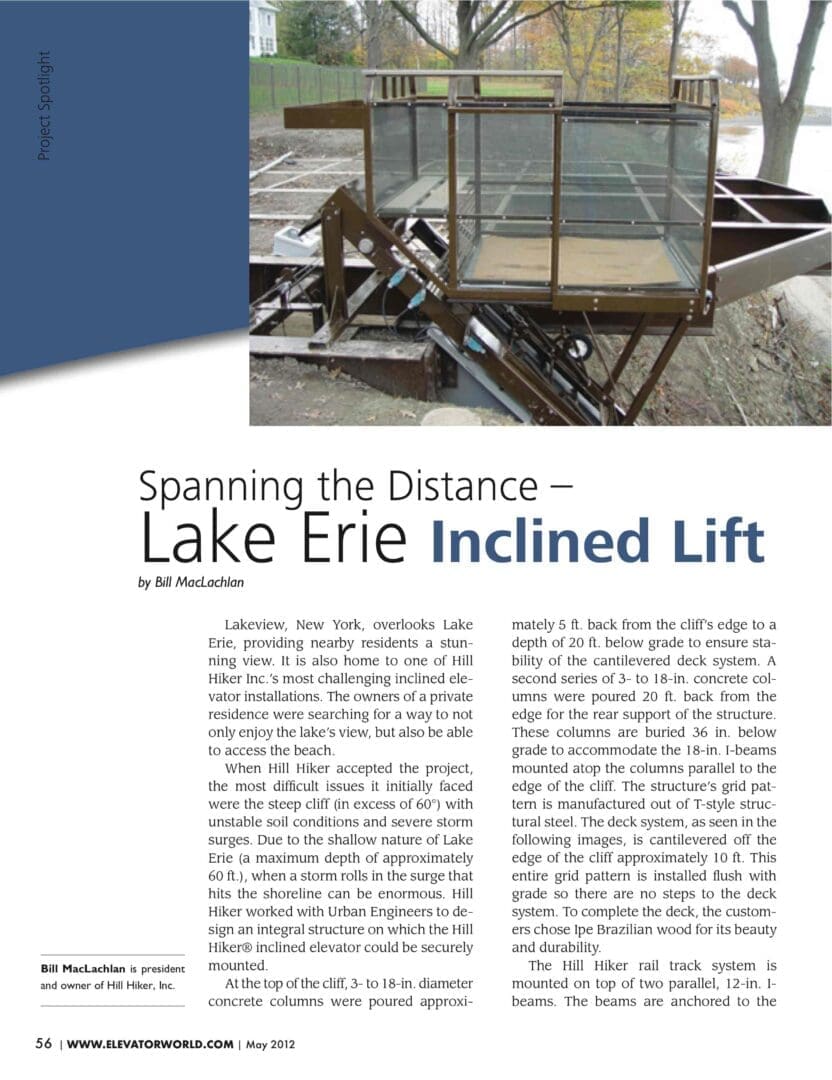
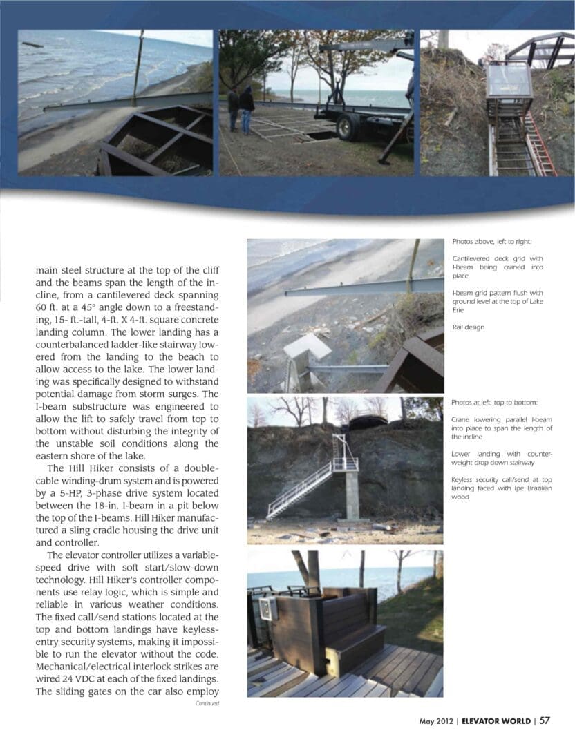
At the top of the cliff, 3- to 18-in. diameter concrete columns were poured approximately 5 ft. back from the cliff’s edge to a depth of 20 ft. below grade to ensure stability of the cantilevered deck system. A second series of 3- to 18-in. concrete columns were poured 20 ft. back from the edge for the rear support of the structure. These columns are buried 36 in. below grade to accommodate the 18-in. I-beams mounted atop the columns parallel to the edge of the cliff. The structure’s grid pattern is manufactured out of T-style structural steel. The deck system, as seen in the following images, is cantilevered off the edge of the cliff approximately 10 ft. This entire grid pattern is installed flush with
grade so there are no steps to the deck system. To complete the deck, the customers chose Ipe Brazilian wood for its beauty and durability.
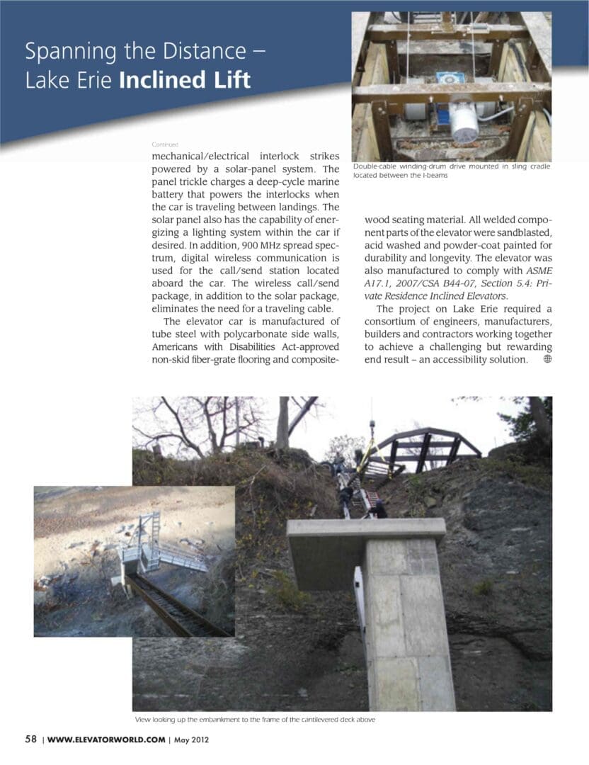
The Hill Hiker rail track system is mounted on top of two parallel, 12-in. Ibeams. The beams are anchored to the main steel structure at the top of the cliff and the beams span the length of the incline, from a cantilevered deck spanning 60 ft. at a 45° angle down to a freestanding, 15- ft.-tall, 4-ft. X 4-ft. square concrete landing column. The lower landing has a counterbalanced ladder-like stairway lowered from the landing to the beach to allow access to the lake. The lower landing was specifically designed to withstand potential damage from storm surges. The I-beam substructure was engineered to allow the lift to safely travel from top to bottom without disturbing the integrity of the unstable soil conditions along the eastern shore of the lake.
The Hill Hiker consists of a double cable winding-drum system and is powered by a 5-HP, 3-phase drive system located between the 18-in. I-beam in a pit below the top of the I-beams. Hill Hiker manufactured a sling cradle housing the drive unit and controller.
The elevator controller utilizes a variable speed drive with soft start/slow-down technology. Hill Hiker’s controller components use relay logic, which is simple and reliable in various weather conditions. The fixed call/send stations located at the top and bottom landings have keyless entry security systems, making it impossible to run the elevator without the code. Mechanical/electrical interlock strikes are wired 24 VDC at each of the fixed landings. The sliding gates on the car also employ mechanical/electrical interlock strikes powered by a solar-panel system. The panel trickle charges a deep-cycle marine battery that powers the interlocks when the car is traveling between landings. The solar panel also has the capability of energizing a lighting system within the car if desired. In addition, 900 MHz spread spectrum, digital wireless communication is used for the call/send station located aboard the car. The wireless call/send package, in addition to the solar package, eliminates the need for a traveling cable. The elevator car is manufactured of tube steel with polycarbonate side walls, Americans with Disabilities Act-approved non-skid fiber-grate flooring and composite wood seating material. All welded component parts of the elevator were sandblasted, acid washed and powder-coat painted for durability and longevity. The elevator was also manufactured to comply with ASME A17.1, 2007/CSA B44-07, Section 5.4: Private Residence Inclined Elevators. The project on Lake Erie required a consortium of engineers, manufacturers, builders and contractors working together to achieve a challenging but rewarding end result – an accessibility solution.
Source:
MacLachlan, Bill. “Spanning the Distance –Lake Erie Inclined Lift.” Elevator World, May 2012, pp. 56-58.