Learn more about the Patuxent River Park located in Maryland.
Learn more about Elevator World, the top trade magazine for the Elevator Industry.
(Note – Article text is also provided below article pages for easier reading on certain devices)

More Project Pictures & Video
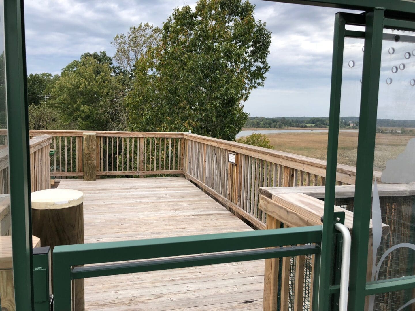
The View From the Top
Inclined Elevators
UpperMarlboro, Maryland
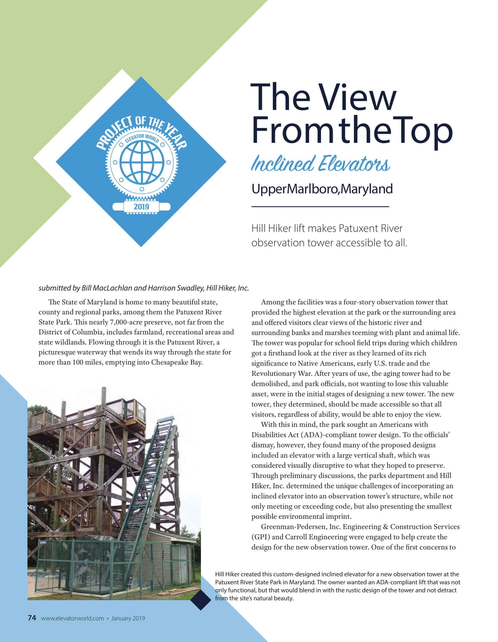
Hill Hiker lift makes Patuxent River observation tower accessible to all.
submitted by Bill MacLachlan and Harrison Swadley, Hill Hiker, Inc.
The State of Maryland is home to many beautiful state, county and regional parks, among them the Patuxent River State Park. This nearly 7,000-acre preserve, not far from the District of Columbia, includes farmland, recreational areas and state wildlands. Flowing through it is the Patuxent River, a picturesque waterway that wends its way through the state for more than 100 miles, emptying into Chesapeake Bay.
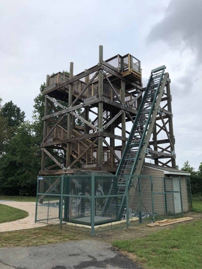
Among the facilities was a four-story observation tower that provided the highest elevation at the park or the surrounding area and offered visitors clear views of the historic river and surrounding banks and marshes teeming with plant and animal life. The tower was popular for school field trips during which children got a firsthand look at the river as they learned of its rich significance to Native Americans, early U.S. trade and the Revolutionary War. After years of use, the aging tower had to be demolished, and park officials, not wanting to lose this valuable asset, were in the initial stages of designing a new tower. The new tower, they determined, should be made accessible so that all visitors, regardless of ability, would be able to enjoy the view.
With this in mind, the park sought an Americans with Disabilities Act (ADA)-compliant tower design. To the officials’ dismay, however, they found many of the proposed designs included an elevator with a large vertical shaft, which was considered visually disruptive to what they hoped to preserve. Through preliminary discussions, the parks department and Hill Hiker, Inc. determined the unique challenges of incorporating an inclined elevator into an observation tower’s structure, while not only meeting or exceeding code, but also presenting the smallest possible environmental imprint.
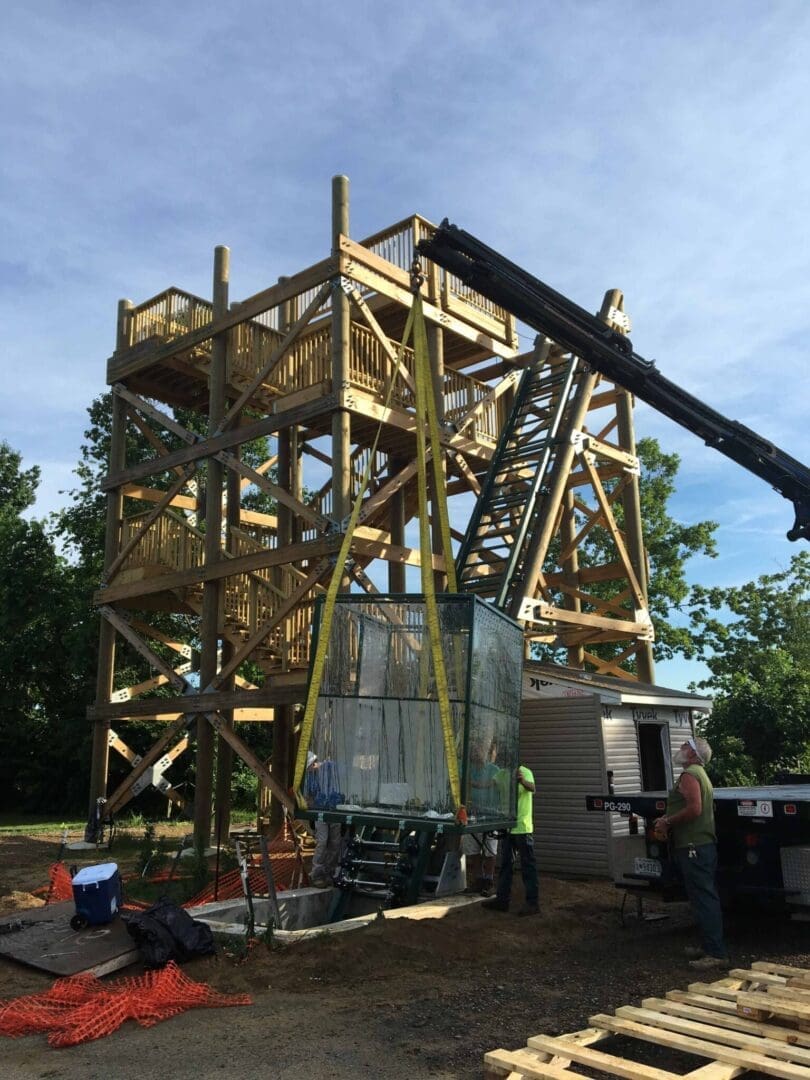
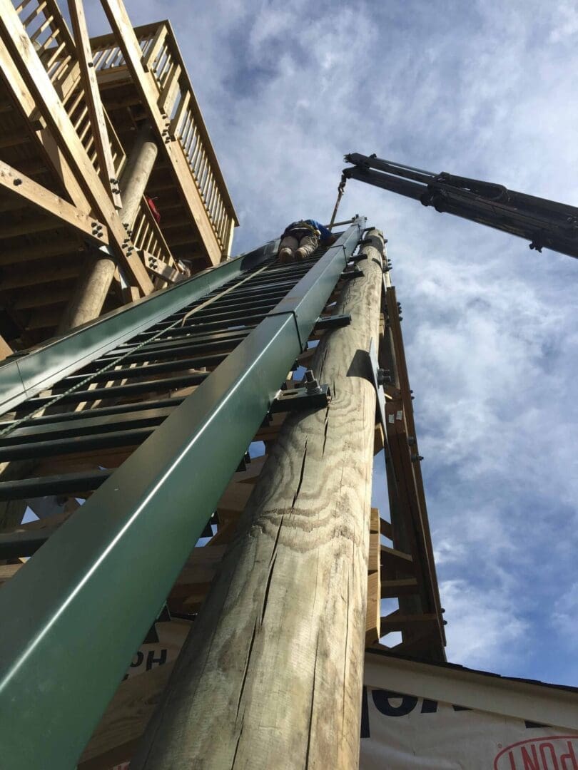
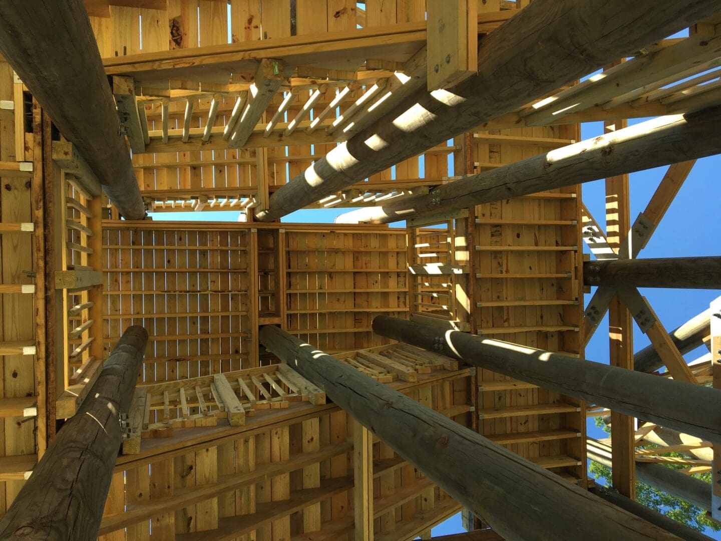
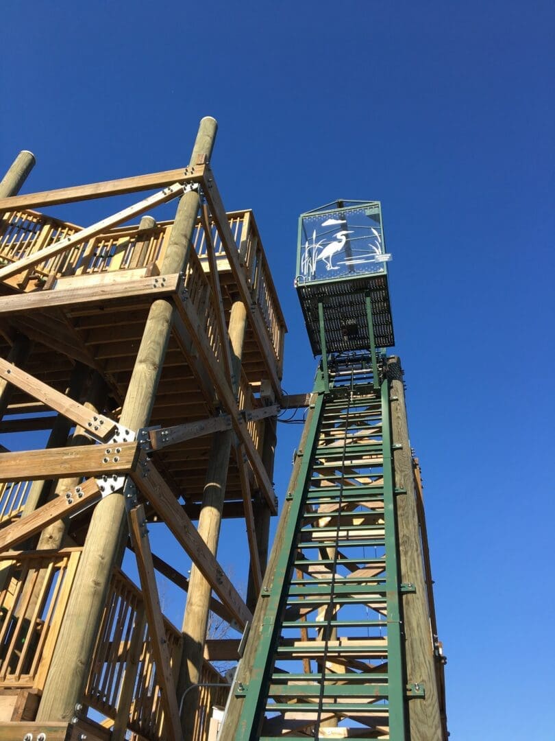
Greenman-Pedersen, Inc. Engineering & Construction Services (GPI) and Carroll Engineering were engaged to help create the design for the new observation tower. One of the first concerns to be addressed and solved for the addition of the Hill Hiker Inclined Elevator System was how to integrate the lift in a structurally sound but aesthetically pleasing way. After some discussion and input from Hill Hiker, it was decided that the support structure should be made to match the timber support structure of the observation tower. Hill Hiker redesigned its standard commercial track to be affixed to the timbers. The park provided two parallel 12-in. diameter timbers that were set 4 ft., 6 in. apart. The tops of the timbers were supported by two 12-in.-thick, 35-ft.-tall vertical support timbers that were set into 8-ft.-deep, 3-ft.-wide concrete footings. The bottoms of the timbers were bolted into clevis mounts, and the top supports and bottom mounts were set 20 ft. apart to create a 60° angle of incline. The use of the timbers allowed the track to not seem out of place in the wooded area. Hill Hiker created a bracket to support the full load of the car, while keeping the track stable and properly aligned, and through-bolted the track to the timbers.
The second major issue was code compliance. ASME A17.1, Section 5.1 requires the elevator car’s onboard controls to be powered by a traveling cable, but park officials were concerned with limiting noise as much as possible. Hill Hiker designed a separate chassis for the traveling cable to address this concern. The chassis runs before the car on the downhill end and has a profile low enough to tuck under the spring buffers. The cable provides hardwired directional controls, lighting, emergency stop (key operated) and an in-car, one-button emergency phone. The chassis is nearly silent and hardly noticeable.
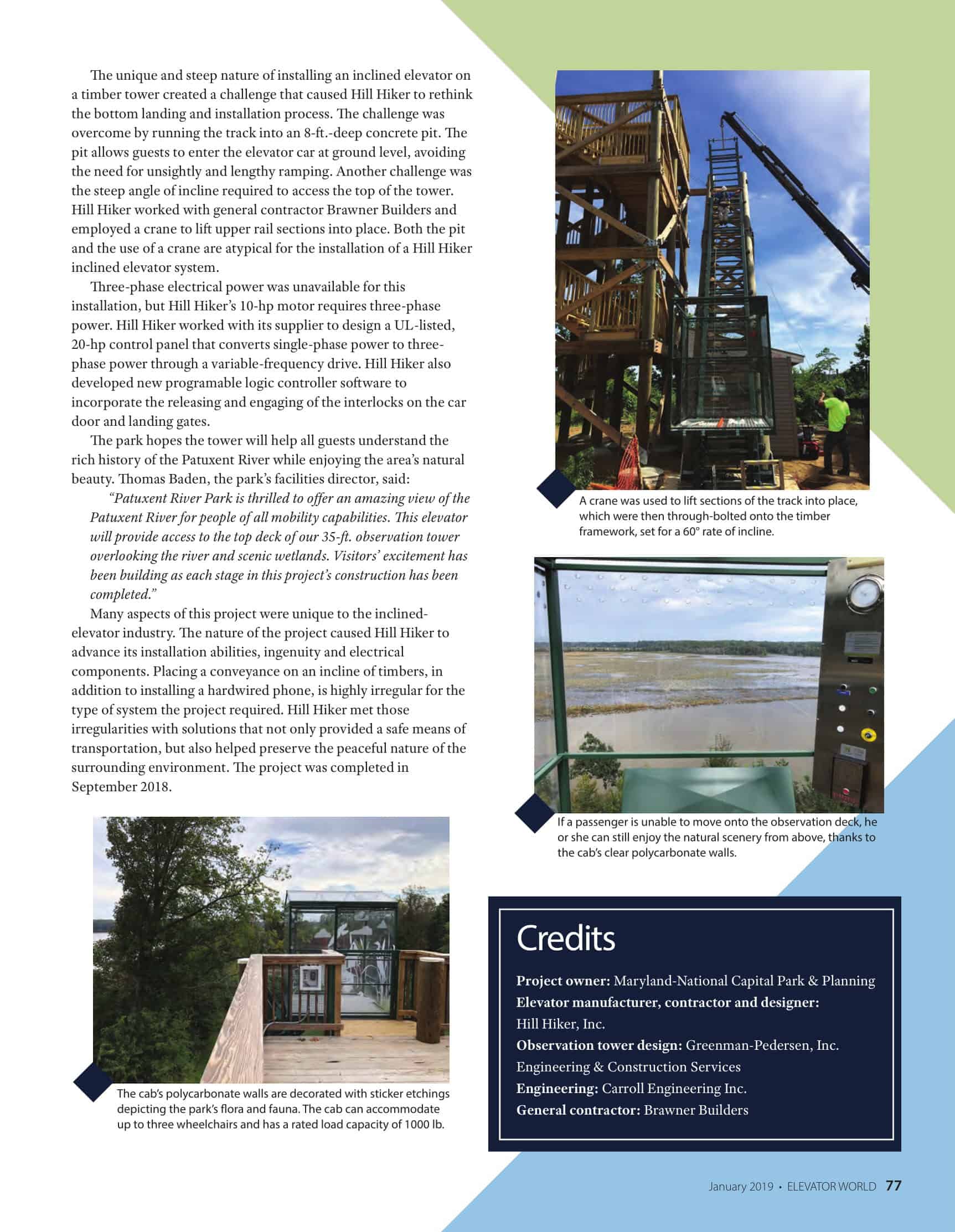
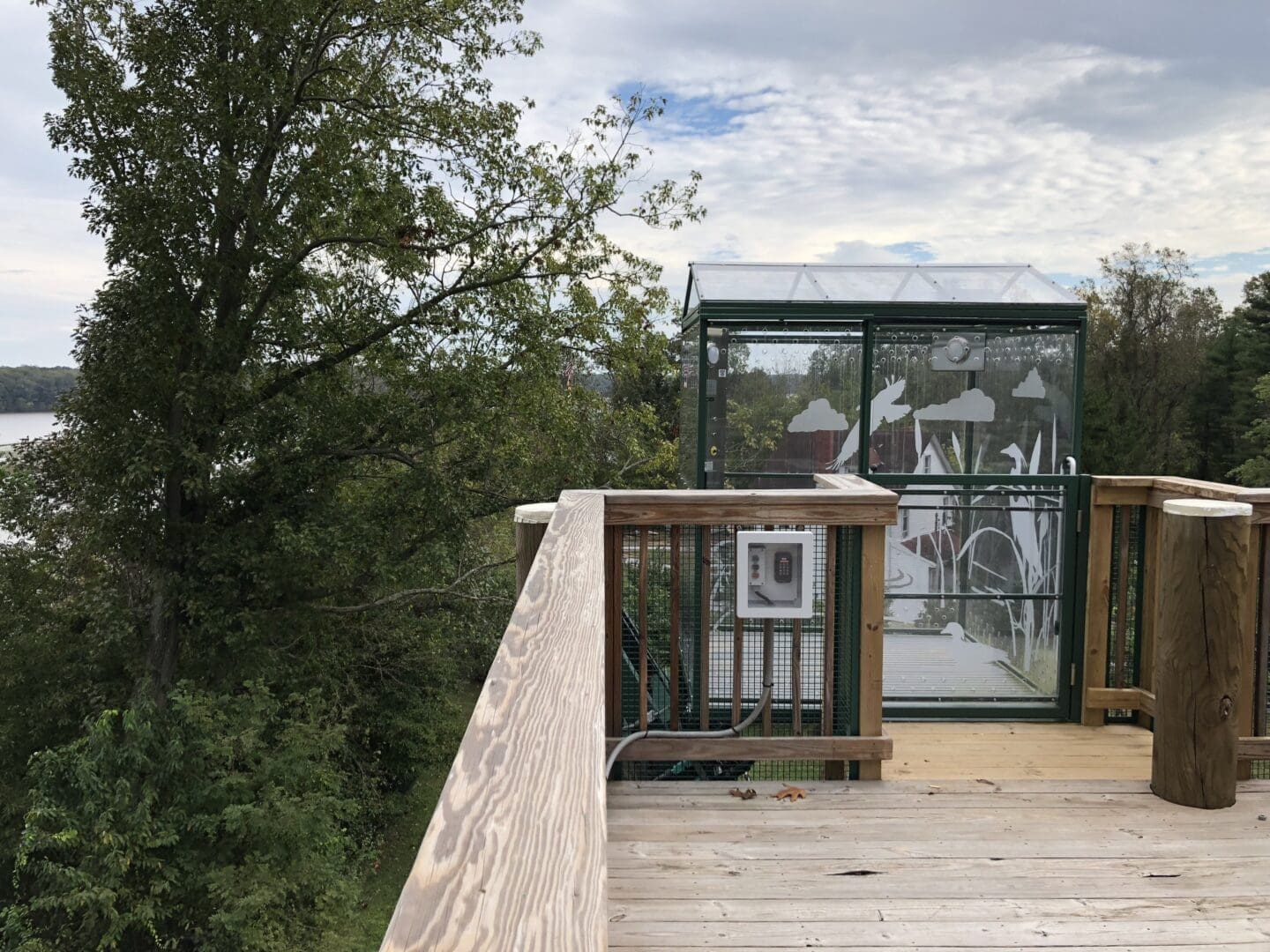
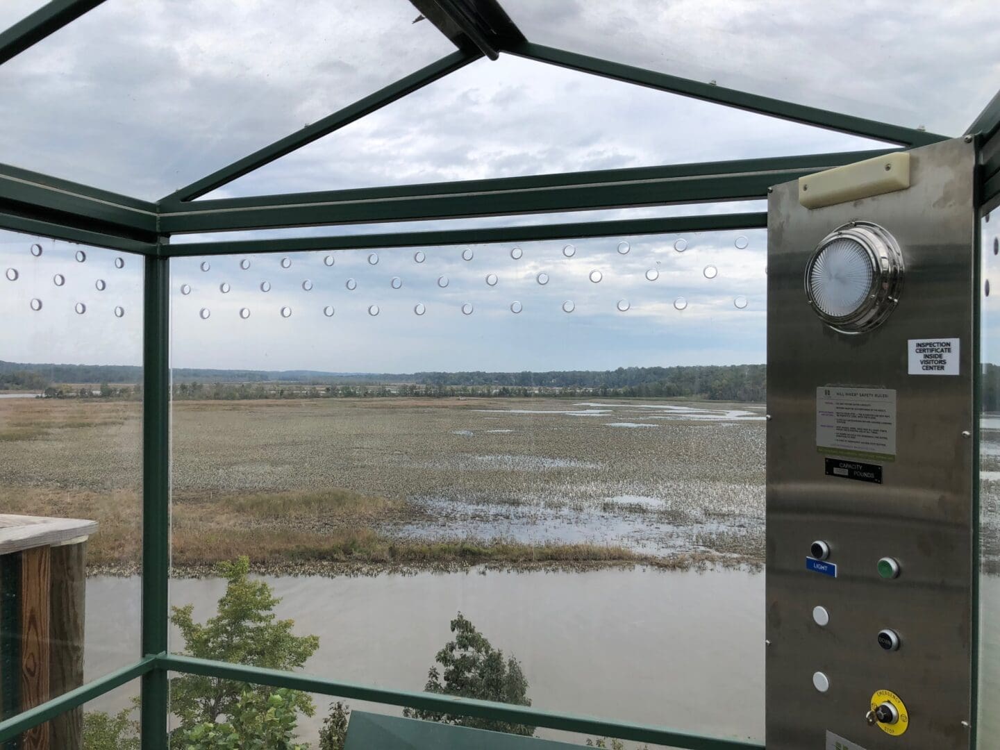
Because the park wanted to include everyone, Hill Hiker designed a car that complies with the ADA. The fully enclosed car features 25 sq. ft. of usable floor space — large enough to fit up to three wheelchairs. Hill Hiker also designed the car with clear polycarbonate wall panels allowing a full panorama of the scenic view. The park decorated the polycarbonate with sticker etchings of the flora and fauna native to the area.
As with any elevator, the customer wanted an exceedingly safe lift system. The safeties were designed to handle a load two-and-ahalf times the elevator’s rated load of 1000 lb. Hill Hiker designed and tested knurl binders-style A safeties that could instantly stop a 2500-lb. load going at a rate of 85 fpm on a 70° incline. These safeties were tested, witnessed and approved by a professional engineer. With a setup comprising an oversized knurl and pillow block bearings, all involved were satisfied that riders would be safe in emergency situations.
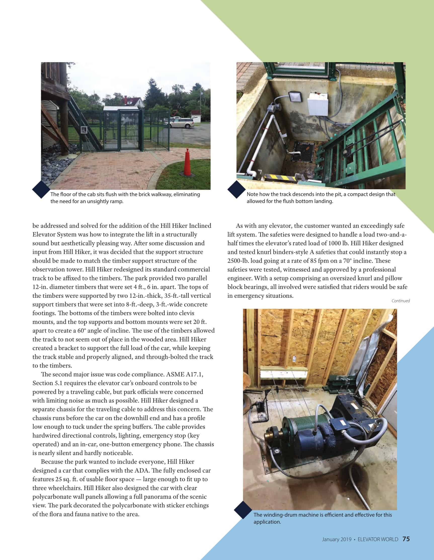
The unique and steep nature of installing an inclined elevator on a timber tower created a challenge that caused Hill Hiker to rethink the bottom landing and installation process. The challenge was overcome by running the track into an 8-ft.-deep concrete pit. The pit allows guests to enter the elevator car at ground level, avoiding the need for unsightly and lengthy ramping. Another challenge was the steep angle of incline required to access the top of the tower. Hill Hiker worked with general contractor Brawner Builders and employed a crane to lift upper rail sections into place. Both the pit and the use of a crane are atypical for the installation of a Hill Hiker inclined elevator system.
Three-phase electrical power was unavailable for this installation, but Hill Hiker’s 10-hp motor requires three-phase power. Hill Hiker worked with its supplier to design a UL-listed, 20-hp control panel that converts single-phase power to three phase power through a variable-frequency drive. Hill Hiker also developed new programable logic controller software to incorporate the releasing and engaging of the interlocks on the car door and landing gates.
The park hopes the tower will help all guests understand the rich history of the Patuxent River while enjoying the area’s natural beauty. Thomas Baden, the park’s facilities director, said:
“Patuxent River Park is thrilled to offer an amazing view of the Patuxent River for people of all mobility capabilities. This elevator will provide access to the top deck of our 35-ft. observation tower overlooking the river and scenic wetlands. Visitors’ excitement has been building as each stage in this project’s construction has been completed.”
Many aspects of this project were unique to the inclined elevator industry. The nature of the project caused Hill Hiker to advance its installation abilities, ingenuity and electrical components. Placing a conveyance on an incline of timbers, in addition to installing a hardwired phone, is highly irregular for the type of system the project required. Hill Hiker met those irregularities with solutions that not only provided a safe means of transportation, but also helped preserve the peaceful nature of the surrounding environment. The project was completed in September 2018.
Material Specifications
♦ Steel conforms to ASTM A240 Fy (force to yield) = 43,200 psi
♦ Machine bolts are Grade 18-8 Stainless Steel
♦ Welding used E71T-11 AWS Classification
General Information
♦ Safety code: ASME A17.1, Section 5.1, Inclined Elevators
♦ Driving means: Galvanized aircraft cable
♦ Rated speed: 55 fpm
♦ Angle of incline: 60°
Motor Area/Room
♦ Height drawings available
♦ Disconnect switch in sight of motor
♦ Workspace for disconnect and controller disconnect within reach of the panel
Car Ropes
♦ Number of ropes: two
♦ Roping ratio: winding-drum drive
♦ Type, size and material: 3/8-in. 7 X 19 galvanized aircraft cable with rated breaking strength of 14,400 lb.
Loads
♦ Car/chassis weight: 1,250 lb.
♦ Rated load: 1,000 lb.
Other Specifications
Track
♦ Track length: Approximately 55 ft.
♦ Support structure: Timbers mounted 8 ft. into ground
Car
♦ Platform material: Marine-grade, ADA-acceptable fiber-grate material
♦ Frame material: Steel
♦ Height of car: 92 in.
♦ Outside car width: 64.5 in.
♦ Outside car length: 64.5 in.
♦ Construction of car door: Steel frame, polycarbonate panels
Drive System
♦ Motor: 10 HP, three-phase, 60 Hz, 240 V
♦ Electromagnetic brake: 220-VAC single-phase 60-Hz line in
♦ Main disconnect: 100-A, two-pole
♦ Main fuse size/type: BOA 600-V UL Type T or CC fast-acting
♦ Conductor size (line/motor): 4/6 AWG
♦ Gearbox: 10 hp; 150:1 ratio
Elevator Controller/Controls
♦ Variable-speed AC motor drive soft start/soft slowdown
♦ Call/send stations: Top, bottom and onboard car with keyless security at top and bottom
Safety System
♦ Limit switches: Deceleration, directional and terminal switches at top and bottom of hill
♦ Emergency-stop buttons: Top, bottom and onboard the car
♦ Track system: Captured rail design
♦ Slack cable system: At motor and onboard car
♦ Overspeed: Centrifugal governor located on car
♦ Pit switches: two
♦ Spring buffer: Located on the track
♦ Car door and gates: Electrical interlock strikes
♦ Emergency communication: Hardwired, onboard one-button phone
♦ Emergency lighting: Two hardwired onboard LED lights
Description of Transportation System
Hill Hiker, Inc., a Minneapolis-based company, manufactured and installed the conveyance in Upper Marlboro, Maryland. The length of travel is 55 ft. with a vertical rise of 35 ft. It travels at a speed of 55 fpm and services two stops. The drive machine is a double-cable winding drum. The drum machine, through a series of deflation sheaves, pulls the car through a C-channel rail. The chassis holds three sets of safeties: an overspeed centrical governor wheel that rides on top of the track with the car and slack-rope safeties connected to each cable. Another slack-rope safety is mounted near the drum. If either cable goes slack, the switch will immediately cut power, engaging the motor’s brakes. Hill Hiker installed interlock strikes on both gates and the car door. The interlock strikes lock the doors and function as an electrical contact safety.
The car is 64.5 in. X 64.4 in. and fully enclosed. The car is mounted to a 4-ft.-X-6-ft. chassis. The track and car are 3/16-in. standard steel construction. The car is suspended by two 3/8-in. galvanized aircraft cables with breaking strength of 14,400 lb. Directional buttons, a phone, a key-operated stop button and LED lighting are mounted inside the cab, and all the car’s onboard systems are hardwired by means of a traveling cable. The traveling cable is suspended with its own chassis, which travels before the car. All gates and doors are locked by an interlock strike.
Hardwired bottoms are located at each landing and protected by a keyless entry pad. The driving machine is of the winding-drum type and is controlled by a UL-listed control panel.
Credits
Project owner: Maryland-National Capital Park & Planning
Elevator manufacturer, contractor and designer: Hill Hiker, Inc.
Observation tower design: Greenman-Pedersen, Inc. Engineering & Construction Services
Engineering: Carroll Engineering Inc.
General contractor: Brawner Builders
Source:
MacLachlan, Bill. “The View From the Top.” Elevator World, Jan. 2019, pp. 74-77.